
The LoRa Protocol
Overview
LoRa is short for “Long Range”. LoRa modulation scheme is a modulation technique combined with a data encoding technique that gives a broad-band spread-spectrum radio the receive sensitivity of a very narrow-band long range radio. Many people are not looking into what is LoRa, and this document describes LoRa and the advantages the LoRa technology has brought to the communication world.
LoRa techniques give LoRa receivers unprecedented sensitivity levels. LoRa radio modems can receive signals 10 times weaker than most radios.
When a receiver’s sensitivity is increased by 10 times, that is the same communication range improvement as increasing the transmitter power 10 times. But with LoRa you get the great range improvements without any increase in power consumption or transmitter power. And most license-free bands restrict transmit power, so LoRa is the best way to increase the communication range of a wireless data link.
Raveon is one of the many early implementers of the LoRa technology in the USA, and one of the first to get a full-power LoRa device FCC certified. LoRa is a radio modulation technique and protocol that enables a device to have an unprecedented long-range. See our LoRa products at www.iot.raveon.com
Forward Error Correction
FEC is commonly used to increase a receiver’s sensitivity by reducing the bit-error rate of the system. LoRa radios have integrated FEC into the protocol. FEC effectively increases the energy per bit and enables the device to correct for bit errors. By adding extra overhead bits to groups of bits being transmitted, the data throughput gets reduces but the bit-error-rate is lower with weak signals, increasing the sensitivity of the receiver.
Interference Immunity
There are a number of different types of interference all wireless systems must deal with:
- Co-channel interference. This is where there is some other transmitter on the exact same frequency that the system is currently utilizing. Many RF systems stop working if the interference is even 10dB weaker than the signal being received. With LoRa, the interference can be as much as 19dB larger than the signal being received and the receiver will still get the signal. This means LoRa systems will keep working reliably as the frequency channels get crowded.
- Blocking Rejection. Sometimes a system needs to operate in a location where there is a powerful interfering signal nearby. For example, in the USA the 906-924MHz ISM band that LoRa uses is only 50mHz away from the 800MHz radio bands where powerful narrow-band transmitters emit 100watts, or 2watt cellular 869-894MHz transmitters. Even though LoRa is 10 time more sensitive, it is even 20 X less susceptible to overload from these powerful out of band signals.
Link Margin Comparison
When one compares a LoRa radio system to a traditional UHF or VHF radio modem, we see that the communication range for LoRa is very similar to VHF and UHF, but it achieves this with much less RF power. The spreadsheet calculations below show the theoretical link margin for LoRa 900MHz compared to VHF and UHF radio systems.
| LoRa 200mW | LoRa 10mW | UHF 2W | VHF2W | |
| Operating Frequency (MHz) | 915 | 915 | 460 | 160 |
| Transmitter Output Power | 23 dBm | 10 dBm | 33 dBm | 33 dBm |
| Link Distance, km | 180 km | 40 km | 150 km | 450 km |
| Link Distance, miles | 111 mi | 24 mi | 93 mi | 279 mi |
| Transmit Antenna Gain (dBi) | 5 | 5 | 3 | 3 |
| Antenna feed loss (both ends) | 1 dB | 1 dB | 1 dB | 1 dB |
| Receive Antenna Gain (dBi) | 5 | 5 | 3 | 3 |
| Receiver Sensitivity | -128dBm | -128dBm | -115dBm | -115dBm |
| System Gain (dB) | 151 | 138 | 148 | 148 |
| Link Fade Margin (dB) | 22.2 | 22.3 | 22.8 | 22.4 |
| Link Path Loss (dB) | -136.8 | -123.7 | -129.2 | -129.6 |
| Effective Radiated Power | 27 | 14 | 35 | 35 |
The theoretical calculations show that a 200mW LoRa radio will work about as long-range as a 2watt UHF radio. A 2watt VHF will work a bit longer range but it is using 2 watts. Raveon’s field tests support these theoretical calculations. We’ve seen VHF and UHF reliably go 50-100 miles line of site, and LoRa can easily go 20-50 miles (at 1/10th the power consumption).
Although, building, forest, and foliage penetration is much better with VHF and UHF radio technology, so 900MHz systems will typically require taller antennas at the base stations and more base stations to get good coverage. This is offset by the cost and power of LoRa radios being so much lower than traditional VHF and UHF systems so building out large area networks with LoRa is a very good approach.
LoRa Modulation
The over-the-air modulation method that LoRa uses is a type of Direct Sequence Spread Spectrum (DSSS) they call Chirp Spread Spectrum (CSS). Each bit is spread by a chipping factor. The number of chips per bit is called the spread factor. Lora also sweeps the modulation across the channel, so that the occupied bandwidth of the transmitted signal matches the choose bandwidth.
The larger the spreading factor, the slower the over-the-air data rate. And as mentioned before, the slower the data rate, the better the receiver sensitivity and the longer the potential communication range. For an example, here is how a spreading factor of 7 affects the bits sent over the air.

Typically, a LoRa radio uses 125kHz, 250kHz, or 500kHz radio channels.Below is a table showing the over-the-air data rates at the various commons spreading factors LoRa uses on these three channel bandwidths.
LoRa Over the Air (OtA) Baud Rates
The OtA data rates listed below are in kilobits per second. This table assumes the LoRa coding chip rate is set to 1.
| Spreading Factor | 125kHz B.W. | 250 kHz B.W. | 500 kHz B.W. |
| 5 | 15.625 | 31.25 | 62.5 |
| 6 | 9.375 | 18.75 | 37.5 |
| 7 | 5.46875 | 10.9375 | 21.875 |
| 8 | 3.125 | 6.25 | 12.5 |
| 9 | 1.757813 | 3.515625 | 7.03125 |
| 10 | 0.976563 | 1.953125 | 3.90625 |
| 11 | 0.537109 | 1.074219 | 2.148438 |
| 12 | 0.292969 | 0.585938 | 1.171875 |
LoRa RF Power Output
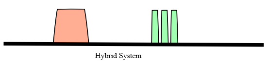
In the USA, LoRa systems typically use a combination frequency hopping and direct sequence modes, to keep in compliance with FCC requirements. A hybrid system can use some 125kHz channels and one direct sequence as long as the power limits and dwell limits of the regulations are met.
To keep the transmit power level in compliance with the PSD limits, a 125kHz channel has 41 3kHz windows, so the max power is 41 X 6.3mW = 258mW (24dBm). If 500kHz channels are used, then the transmit power can be 4X that (1watt) on the 500kHz channel. To account for modulation peaks and some bandwidth margins, typical LoRa power levels are about ½ the theoretical limit which will ensure regulatory compliance.
Multi-Channel
Raveon’s LoRa base stations utilize LoRa chips that have the ability to receive 8 channels all at the same time. No other long-range wireless technology has this multi-channel receiver capability.
By having the ability to receive 8 channels, 8 wireless nodes can report in at the same time, and as long as they are on different RF channels, the base station can receive them.
LoRaWAN Frequencies
The LoRaWAN protocol specifies that certain frequencies in certain countries shall be supported by every device. These are listed as:
- EU 868.1, 868.3, and 868.5 MHz
- EU 433.175, 433.375 and 433.575 MHz
- China 779.5, 779.7 and 779.9 MHz.
- North America US 902-928MHz.
Be sure to visit the Raveon Blog for more information.
