AN236 Summary
Electronic communications is all about interlinking circuits (processors or other integrated circuits) to create a symbiotic system. For those individual circuits to swap information, they must share a common standard communication protocol. Many communication protocols have been designed to achieve data exchange.
The most common serial communication protocols are RS232, RS485, RS422, USB, and Ethernet. But because USB and Ethernet require powerful interfaces with complex protocols, many efficient devices utilized RS232, RS485, and RS422 which is what this note is all about.
Protocol Comparison Chart
|
RS-232 |
RS-422 |
RS-485 |
| Cable |
Single ended |
Single ended multi-drop |
Multi-drop |
| Number of Devices |
1 transmitter
1 receiver |
1 transmitter
10 receivers |
32 transmitters
32 receivers |
| Communication Mode |
Full duplex |
Full duplex,
Half duplex |
Full duplex,
Half duplex |
| Maximum Distance |
50 feet at 19.2 kbps |
4000 feet at 100 kbps |
4000 feet at 100 kbps |
| Max Data Rate (50 feet) |
1 mbps |
10 mbps |
10 mbps |
Serial Protocols
The RS232, RS485, RS422 serial protocols only relate to the hardware interface, not the software protocols used to make the devices communicate. There are many protocols that exist in the market place so one cannot assume interoperability between different manufacturers of “RS232” ports.
To define Instruments that supports a mixture of industry standard and proprietary serial protocols:
Modbus RTU
This protocol is used in industrial applications and most SCADA PLC’s have drivers for Modbus RTU. The Modbus protocol is well published and every manufacturer can and does determine its own addressing scheme. The manufacturer must supply the addressing scheme, register type, and Modbus commands that is supports.
ASCII protocol
ASCII is popular because it is easier than Modbus to write your own driver in a PLC or a PC. Most every manufacturer’s protocols are not usually compatible.
The Advantages of RS485 and RS422 vs RS232
RS485 and RS422 use differentiation. Two wires are required for each signal. The figure below shows a single RS485 / RS422 signal being transmitted. To transmit a logic 1, line B is high and line A is low. To transmit a logic 0, line B is low and line A is high. The advantage of this arrangement is that signals can be transmitted faster and over greater distances than is possible with a single wire.
The main difference between RS422 and RS485 is the types of communications allowed. RS422 allows only one-way (simplex) communications between one driver, and as many as ten receiving devices. To control devices and need no feedback from them, RS-422 multidrop network will work well. RS485 was designed to address the multi-drop limitation of RS422, allowing up to 32 devices to communicate.
RS-232
An RS232 serial bus consists of just two communication wires – one for sending data and another for receiving. As such, serial devices should have two serial pins: the receiver, RX, and the transmitter, TX. Because the communication data is based upon the voltage on the wires, relative to the ground level, a ground connection must be made between devices that communicate with RS-232. Here is an RS232 wiring diagram:

A digital 1 voltage is: -3V to -25V
A digital 0 voltage is: +3V to +25V
RS232 data is sent serially, each bit is sent one after the next because there is only one data line in each direction. This mode of data transmission also requires that the receiver knows when the actual data bits are arriving so that it can synchronize itself to the incoming data. To achieve this a logic 0 is sent as a synchronization start bit.
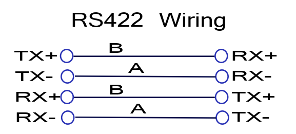
RS422
RS422 is designed to be tolerant of noise and forgiving of long cable runs. It achieves this by using a differential current drive output which has high immunity to noise. The noise immunity enables RS485 systems to operate over very long connections, much better than RS232, US, and Ethernet.
Each signal uses two wires to pass the data. The differential voltage on the A and B wires represent the digital value. If B>A the value is 1. If A>B then value is 0.
| Input Signal |
A B |
Output Signal |
| 0 |
1 0 |
0 |
| 1 |
0 1 |
1 |
RS422A Standard Specifications
- 1 Driver, up to 10 Receivers
Line Length for Max Data Rate:
- 40 Feet = 12m 10 Mbits/sec
- 400 Feet = 122m 1 Mbits/sec
- 4000 Feet = 1219m 100 kbits/sec
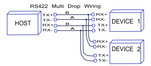
A multi-drop wiring has many desirable advantages, RS422 devices cannot be used to construct a truly multi-point network. A true multi-point network consists of multiple drivers and receivers connected on a single bus, where any node can transmit or receive data. RS422 networks are often used in a half-duplex mode,
RS485
RS485 is still popular. It is similar to the RS422 upon which it is based. The RS485 port has been used for many years. RS485 has many advantages over both RS232 and USB when it comes to applications in noisy industrial environments. RS422 devices can be used on an RS485 bus network if they are only used as recipients.
The main difference between RS422 and RS485 is that up to 32 transmitter receiver pairs may be present on the line at one time on RS485. A 120 Ohm resistor must be used to terminate the main line.
RS485A Standard
- Up to 32 Driver/Receiver Pairs
Line Length Max Data Rate
- 40 Feet = 12m 10 Mbits/sec
- 400 Feet = 122m 1 Mbits/sec
- 4000 Feet = 1219m 100 kbits/sec
When instruments are described as having an RS485 interface this tells you nothing for sure about the signals being transmitted. Usually though only the Transmit Data (TX) and Receive Data (RX) of a normal serial port are converted to RS485 or RS422. The other signals of the serial port are not used. Three arrangements are commonplace: Write only, 4-wire (full duplex) and 2-wire (half duplex). The “2-wire” RS-485 connection is shown below.
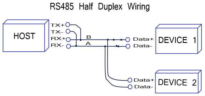 RS485 half-duplex can use just two wires to communicate with up to 32 device, one at a time. Each device has the ability to turn off its output drivers, so only the one device that is linking to the host outputs a signal on its TX lines.
Termination Resistors
Termination resistors should be placed on both ends of the twisted pair of wires. The impedance value should be the same value of the characteristic impedance of the twisted pair and should be placed at the far ends of the cable.
For cables that are 2000 feet or less, a termination resistor is not needed at baud rates of 9600bps or less.
If a termination resister is required, a 120? or greater should be used. No more than 2 termination resistors should be used, one at each end of the RS485 transmission line.

For additional information, contact:
Raveon Technologies Corporation
2320 Cousteau Court
Vista, CA 92081 – USA
Phone: 1-760-444-5995
Fax: 1-760-444-5997
Email: sales@raveon.com