Solutions by Industry

Connecting an M7-GX to a Raymarine Multifunction Display

The M7-GX series of GPS transponders may be directly connected to any Raymarine A, C, E or G series display.  All of these Raymarine displays have at least one NMEA-0183 port. This allows them to be used with Raveon’s RavTrack series of GPS radio transponders to make a complete GPS tracking system. For this article, the Raymarine E80 product will be used as an example but the other models in the Raymarine line have similar integration steps.

Raymarine E80 Map

When connected to the M7-GX GPS radio transponder, the E80 map will show the location of the user plus the location of all other transponders within radio range.  This unique feature allows a user to quickly, easily and inexpensively make a portable AVL system for tracking cars, trucks, race cars, construction equipment or anything Raveon’s M7-GX transponder may be installed on.

The Raymarine displays have a built-in interface for NMEA 0183 devices, a serial data port intended for RS422/RS232 operation. The Raymarine E80 supports RS232 levels on the communications lines as well as the RS422 levels. Since RS422 was designed for differential signaling, there are pairs of signal wires instead of a single-ended ground that is shared between the Rx and Tx lines. For an RS232 protocol, one can tie the two negative wires of the NMEA 0183 signal pairs together to act as the ground.

The NMEA 0183 defaults to 4800 baud, 8 data bits, no parity, 1 stop bit, no handshake (4800-8-N-1).  It is used to exchange way-point and other information between displays, GPS devices, and transponders.

When Raveon’s M7-GX transponder is connected to the Raymarine E80 using the NMEA 0183 connection, the GPS radio transponder can put icons on the screen of the E80. As the transponder receives updated positions from other vehicles, it updates the position of the tracked vehicle icons on the E80 display.

NMEA 0183

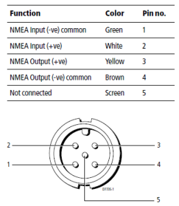
Raymarine E80 Wiring

The Raymarine E80 has the 5-pin NMEA 0183 connector shown to the right, located on the rear of the unit. NMEA 0183 is a common communications format for marine applications. See the following diagram for general wiring connections.

R08005

The recommended cable for interfacing to this NMEA 0183 port is the R08004 NMEA cable. It is a 5-wire cable with an Rx pair (differential + and -), Tx pair (differential + and -) and drain wire (unused). For the case of the E80-M7 system, the only used connections will be the white wire (NMEA input +) and the green wire (NMEA input common). These NMEA 0183 cables come in various forms so make sure to verify that the correct wire pairs (Rx, Tx or both) are included in the cable assembly before purchasing. Here is a picture of the full cable assembly with both Rx and Tx wires:

Wiring the Serial Cable

The E80 NMEA 0183 port must be connected to the M7-GX GPS transponder. This connection will allow the M7-GX to put icons on the screen of the E80 display, showing the location of other tracked vehicles.  The M7-GX GPS transponder uses a 9-pin DB9 as it’s serial connection. Solder the E80 data cable wires onto a DB9 connector and plug the DB9 into the M7 transponder as shown below:

db9     NMEA 0183 connector

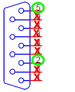
Connect the white wire (NMEA input +, pin 2) on the R08004 cable to the serial data output (pin 2) on M7-GX DB9 connector. Then, connect the green wire (NMEA input -, pin 1) on the R08004 cable to the ground of the M7-GX DB9 connector. You do not need to connect the brown, yellow or braid wires on the R08004 cable so you can trim them off if desired.

Configuring the E80

Verify that the serial data communications are set to 4800 baud-8-N-1 on the E80.

Configuring the M7 GX Transponder

Raveon has a designed the M7 GX transponder to work with the E80 display or any other NMEA 0183 display that can accept the “$GPWPL” NMEA message.   The $GPWPL is an industry standard message that many GPS displays interpret as a waypoint command.  The M7 GX outputs this $GPWPL message to put icons on the screen of the E80, and to move the icons around on its screen.

To configure the M7 transponder to output the $GPWPL message, set the M7 GX to GPS mode 4.  To do this, put it into the configuration mode by send the +++ into the serial port.  The M7 will respond with an OK.  Type GPS 4 and press enter to put it into GPS 4 mode.  GPS 4 is the mode that causes the M7 GX to output $GPWPL messages whenever it receives a status/position message over the air
.

Table: Volts to dBm to Watts

Table of effective power in dBm and watts given RMS voltage or peak-to-peak voltage.


Volts (RMS)   Volts (PEP) dBm (50ohm) Watts (50ohms)
1.000 2.83 -16.990 0.020
1.200 3.39 -15.406 0.029
1.440 4.07 -13.822 0.041
1.728 4.89 -12.239 0.060
2.074 5.87 -10.655 0.086
2.488 7.04 -9.072 0.124
2.986 8.45 -7.488 0.178
3.583 10.1 -5.904 0.257
4.300 12.2 -4.321 0.370
5.160 14.6 -2.737 0.532
6.192 17.5 -1.153 0.767
7.430 21.0 0.430 1.104
8.916 25.2 2.014 1.59
10.699 30.3 3.597 2.29
12.839 36.3 5.181 3.30
15.407 43.6 6.765 4.75
18.488 52.3 8.348 6.84
22.186 62.8 9.932 9.84
26.623 75.3 11.516 14.2
31.948 90.4 13.099 20.4
38.338 108 14.683 29.4
46.005 130 16.266 42.3
55.206 156 17.850 61.0
66.247 187 19.434 87.8
79.497 225 21.017 126.4
95.396 270 22.601 182.0

Table: RF Power Density

RF Power Density vs Distance

The RF power density at any distance from a transmitter that is radiating RF power will depend upon the antenna gain, power into the antenna, and the distance from the antenna.  The table below illustrates haw fast the RF power power density drops off given certain distances from the radiating antenna and the power into the antenna.

11 meters from a 125 watt transmitter is about the same RF power density as 1 meter from a 2 watt transmitter.


Power (dBm) Power (Watts) Antenna Gain (dBi) Antenna Gain Factor Distance (meters) PSD(W/m2)
20 0.10 0 1 0.1 0.796
20 0.10 0 1 0.5 0.032
20 0.10 0 1 1 0.008
20 0.10 0 1 3 0.001
20 0.10 0 1 10 0.000
30 1.00 0 1 0.1 7.962
30 1.00 0 1 0.5 0.318
30 1.00 0 1 1 0.080
30 1.00 0 1 3 0.009
30 1.00 0 1 10 0.001
33 2.00 0 1 0.1 15.886
33 2.00 0 1 0.5 0.635
33 2.00 0 1 1 0.159
33 2.00 0 1 3 0.018
33 2.00 0 1 10 0.002
36 3.98 0 1 0.1 31.696
36 3.98 0 1 0.5 1.268
36 3.98 0 1 1 0.317
36 3.98 0 1 3 0.035
36 3.98 0 1 10 0.003
42 15.85 0 1 0.1 126.186
42 15.85 0 1 0.5 5.047
42 15.85 0 1 1 1.262
42 15.85 0 1 3 0.140
42 15.85 0 1 10 0.013
51 125.89 0 1 0.1 1002.329
51 125.89 0 1 0.5 40.093
51 125.89 0 1 1 10.023
51 125.89 0 1 3 1.114
51 125.89 0 1 10 0.100
54 251.19 0 1 0.1 1999.910
54 251.19 0 1 0.5 79.996
54 251.19 0 1 1 19.999
54 251.19 0 1 3 2.222
54 251.19 0 1 11 0.165

Table: Miles to Kilometers

Miles to Kilometers Conversion Table


Miles km Miles km Miles km Miles km Miles km Miles km Miles km
0.1 0.16 3.1 4.99 6.1 9.82 9.1 14.65 12.1 19.47 15.1 24.30 18.1 29.13
0.2 0.32 3.2 5.15 6.2 9.98 9.2 14.81 12.2 19.63 15.2 24.46 18.2 29.29
0.3 0.48 3.3 5.31 6.3 10.14 9.3 14.97 12.3 19.79 15.3 24.62 18.3 29.45
0.4 0.64 3.4 5.47 6.4 10.30 9.4 15.13 12.4 19.96 15.4 24.78 18.4 29.61
0.5 0.80 3.5 5.63 6.5 10.46 9.5 15.29 12.5 20.12 15.5 24.94 18.5 29.77
0.6 0.97 3.6 5.79 6.6 10.62 9.6 15.45 12.6 20.28 15.6 25.11 18.6 29.93
0.7 1.13 3.7 5.95 6.7 10.78 9.7 15.61 12.7 20.44 15.7 25.27 18.7 30.09
0.8 1.29 3.8 6.12 6.8 10.94 9.8 15.77 12.8 20.60 15.8 25.43 18.8 30.26
0.9 1.45 3.9 6.28 6.9 11.10 9.9 15.93 12.9 20.76 15.9 25.59 18.9 30.42
1 1.61 4 6.44 7 11.27 10 16.09 13 20.92 16 25.75 19 30.58
1.1 1.77 4.1 6.60 7.1 11.43 10 16.25 13.1 21.08 16.1 25.91 19.1 30.74
1.2 1.93 4.2 6.76 7.2 11.59 10 16.42 13.2 21.24 16.2 26.07 19.2 30.90
1.3 2.09 4.3 6.92 7.3 11.75 10 16.58 13.3 21.40 16.3 26.23 19.3 31.06
1.4 2.25 4.4 7.08 7.4 11.91 10 16.74 13.4 21.57 16.4 26.39 19.4 31.22
1.5 2.41 4.5 7.24 7.5 12.07 11 16.90 13.5 21.73 16.5 26.55 19.5 31.38
1.6 2.57 4.6 7.40 7.6 12.23 11 17.06 13.6 21.89 16.6 26.72 19.6 31.54
1.7 2.74 4.7 7.56 7.7 12.39 11 17.22 13.7 22.05 16.7 26.88 19.7 31.70
1.8 2.90 4.8 7.72 7.8 12.55 11 17.38 13.8 22.21 16.8 27.04 19.8 31.87
1.9 3.06 4.9 7.89 7.9 12.71 11 17.54 13.9 22.37 16.9 27.20 19.9 32.03
2 3.22 5 8.05 8 12.87 11 17.70 14 22.53 17 27.36 20 32.19
2.1 3.38 5.1 8.21 8.1 13.04 11 17.86 14.1 22.69 17.1 27.52 20.1 32.35
2.2 3.54 5.2 8.37 8.2 13.20 11 18.02 14.2 22.85 17.2 27.68 20.2 32.51
2.3 3.70 5.3 8.53 8.3 13.36 11 18.19 14.3 23.01 17.3 27.84 20.3 32.67
2.4 3.86 5.4 8.69 8.4 13.52 11 18.35 14.4 23.17 17.4 28.00 20.4 32.83
2.5 4.02 5.5 8.85 8.5 13.68 12 18.51 14.5 23.34 17.5 28.16 20.5 32.99
2.6 4.18 5.6 9.01 8.6 13.84 12 18.67 14.6 23.50 17.6 28.32 20.6 33.15
2.7 4.35 5.7 9.17 8.7 14.00 12 18.83 14.7 23.66 17.7 28.49 20.7 33.31
2.8 4.51 5.8 9.33 8.8 14.16 12 18.99 14.8 23.82 17.8 28.65 20.8 33.47
2.9 4.67 5.9 9.50 8.9 14.32 12 19.15 14.9 23.98 17.9 28.81 20.9 33.64
3 4.83 6 9.66 9 14.48 12 19.31 15 24.14 18 28.97 21 33.80

Table: Coax cable attenuation

Coax cable attenuation.

All coax cable looses power.  The amount of power loss in a coax cable depends upon the length of the cable, the type of cable, and the frequency it is being used at.

The following tables are helpful for predicting the amount of signal loss through a coax cable.  For example, if you use a 50 foot section of LMR-400 cable in your data radio modem system that operates a 450MH, you will loose 1.6dB.

Cable Group Attenuation in dB per 100 feet Outer Diameter (inches)
30 50 100 150 450 1000 2400
LMR-100A® 3.9 5.1 7.2 8.9 15.8 24.1 38.0
LMR-200® 1.8 2.3 3.2 4.0 7.0 10.4 16.5 0.195
LMR-240 Ultra® 1.3 1.7 2.9 3.6 5.3 9.5 12.7 0.240
LMR-240® 1.3 1.7 2.4 3.0 5.2 7.9 12.7 0.240
LMR-400 Ultra® 0.8 1.1 1.5 1.5 3.2 5.0 7.9 0.405
LMR-400® 0.7 0.9 1.3 1.5 2.7 4.1 6.6 0.405
RG-174 5.5 6.6 8.8 10.3 18.1 27.4 43.0 0.100
RG-213 1.0 1.5 2.1 2.8 4.4 7.1 12.0 0.405
RG-214 1.2 1.6 1.9 2.4 5.1 8.0 13.7 0.405
RG-316 4.3 5.6 7.9 4.4 17.2 26.1 45.0 0.110
RG-58A/U 2.5 4.1 5.3 6.1 10.6 24.0 38.9 0.195
RG-8/U FOAM 1.0 1.2 1.8 2.4 4.4 7.1 12.0 0.400
RG-8X 2.0 2.1 3.0 4.7 8.6 12.9 21.6 0.242
RG218/U 0.4 0.6 0.8 1.0 2.0 3.8 6.4 0.870


Cable Group Attenuation in dB per 100 meters Outer Diameter (mm)
30 50 100 150 450 1000 2400
LMR-100A® 12.5 16.3 23.0 28.5 50.6 77.1 121.6
LMR-200® 5.8 7.4 10.2 12.8 22.4 33.3 52.8 4.95
LMR-240 Ultra® 4.2 5.4 9.3 11.5 17.0 30.4 40.6 6.10
LMR-240® 4.2 5.4 7.7 9.6 16.6 25.3 40.6 6.10
LMR-400 Ultra® 2.6 3.4 4.8 4.8 10.2 15.8 25.3 10.29
LMR-400® 2.2 2.9 4.0 4.8 8.6 13.2 21.1 10.29
RG-174 17.6 21.1 28.2 33.0 57.9 87.7 137.6 2.54
RG-213 3.3 4.8 6.7 9.0 14.1 22.6 38.4 10.29
RG-214 3.8 5.1 6.1 7.7 16.3 25.6 43.8 10.29
RG-316 13.8 17.9 25.3 14.1 55.0 83.5 144.0 2.79
RG-58A/U 8.0 13.1 17.0 19.5 33.9 76.8 124.5 4.95
RG-8/U FOAM 3.3 3.8 5.8 7.7 14.1 22.7 38.4 10.16
RG-8X 6.4 6.7 9.6 15.0 27.5 41.3 69.1 6.15
RG218/U 1.3 1.8 2.6 3.3 6.5 12.2 20.5 22.10

Table: uV to dBm 50 and 75ohm

The following table lists RF power levels given various RMS voltages. It converts uV to dBm with either a 50 ohm load or 75 ohm load.


uV dBm (50ohm) dBm (75ohm) fW (50ohm) fW (75ohm)
0.050 -133.010 -134.771 0.050 0.033
0.055 -132.182 -133.943 0.061 0.040
0.061 -131.355 -133.116 0.073 0.049
0.067 -130.527 -132.288 0.089 0.059
0.073 -129.699 -131.460 0.107 0.071
0.081 -128.871 -130.632 0.130 0.086
0.089 -128.043 -129.804 0.157 0.105
0.097 -127.215 -128.976 0.190 0.127
0.107 -126.387 -128.148 0.230 0.153
0.118 -125.560 -127.321 0.278 0.185
0.130 -124.732 -126.493 0.336 0.224
0.143 -123.904 -125.665 0.407 0.271
0.157 -123.076 -124.837 0.492 0.328
0.173 -122.248 -124.009 0.596 0.397
0.190 -121.420 -123.181 0.721 0.481
0.209 -120.592 -122.353 0.872 0.582
0.230 -119.765 -121.526 1.056 0.704
0.253 -118.937 -120.698 1.277 0.852
0.278 -118.109 -119.870 1.546 1.030
0.306 -117.281 -119.042 1.870 1.247
0.336 -116.453 -118.214 2.263 1.509
0.370 -115.625 -117.386 2.738 1.825
0.407 -114.798 -116.558 3.313 2.209
0.448 -113.970 -115.731 4.009 2.673
0.492 -113.142 -114.903 4.851 3.234
0.542 -112.314 -114.075 5.870 3.913
0.596 -111.486 -113.247 7.102 4.735
0.655 -110.658 -112.419 8.594 5.729
0.721 -109.830 -111.591 10.398 6.932
0.793 -109.003 -110.763 12.582 8.388
0.872 -108.175 -109.936 15.224 10.149
0.960 -107.347 -109.108 18.421 12.281
1.056 -106.519 -108.280 22.290 14.860
1.161 -105.691 -107.452 26.970 17.980
1.277 -104.863 -106.624 32.634 21.756
1.405 -104.035 -105.796 39.487 26.325
1.546 -103.208 -104.968 47.780 31.853
1.700 -102.380 -104.141 57.813 38.542
1.870 -101.552 -103.313 69.954 46.636
2.057 -100.724 -102.485 84.645 56.430
2.263 -99.896 -101.657 102.420 68.280
2.489 -99.068 -100.829 123.928 82.619
2.738 -98.240 -100.001 149.953 99.969
3.012 -97.413 -99.174 181.443 120.962
3.313 -96.585 -98.346 219.546 146.364
3.645 -95.757 -97.518 265.651 177.101
4.009 -94.929 -96.690 321.438 214.292
4.410 -94.101 -95.862 388.940 259.293
4.851 -93.273 -95.034 470.617 313.745
5.336 -92.445 -94.206 569.447 379.631
5.870 -91.618 -93.379 689.031 459.354
6.456 -90.790 -92.551 833.727 555.818
7.102 -89.962 -91.723 1008.810 672.540
7.812 -89.134 -90.895 1220.660 813.773
8.594 -88.306 -90.067 1476.998 984.666
9.453 -87.478 -89.239 1787.168 1191.445
uV dBm (50ohm) dBm (75ohm) mW (50ohm) mW (75ohm)
10.000 -86.990 -88.751 0.000002 0.000001
11.000 -86.162 -87.923 0.000002 0.000002
12.100 -85.334 -87.095 0.000003 0.000002
13.310 -84.506 -86.267 0.000004 0.000002
14.641 -83.678 -85.439 0.000004 0.000003
16.105 -82.850 -84.611 0.000005 0.000003
17.716 -82.023 -83.783 0.000006 0.000004
19.487 -81.195 -82.956 0.000008 0.000005
21.436 -80.367 -82.128 0.000009 0.000006
23.579 -79.539 -81.300 0.000011 0.000007
25.937 -78.711 -80.472 0.000013 0.000009
28.531 -77.883 -79.644 0.000016 0.000011
31.384 -77.055 -78.816 0.000020 0.000013
34.523 -76.228 -77.989 0.000024 0.000016
37.975 -75.400 -77.161 0.000029 0.000019
41.772 -74.572 -76.333 0.000035 0.000023
45.950 -73.744 -75.505 0.000042 0.000028
50.545 -72.916 -74.677 0.000051 0.000034
55.599 -72.088 -73.849 0.000062 0.000041
61.159 -71.260 -73.021 0.000075 0.000050
67.275 -70.433 -72.194 0.000091 0.000060
74.002 -69.605 -71.366 0.000110 0.000073
81.403 -68.777 -70.538 0.000133 0.000088
89.543 -67.949 -69.710 0.000160 0.000107
100.000 -66.990 -68.751 0.000200 0.000133
110.000 -66.162 -67.923 0.000242 0.000161
121.000 -65.334 -67.095 0.000293 0.000195
133.100 -64.506 -66.267 0.000354 0.000236
146.410 -63.678 -65.439 0.000429 0.000286
161.051 -62.850 -64.611 0.000519 0.000346
177.156 -62.023 -63.783 0.000628 0.000418
194.872 -61.195 -62.956 0.000759 0.000506
214.359 -60.367 -62.128 0.000919 0.000613
235.795 -59.539 -61.300 0.001112 0.000741
259.374 -58.711 -60.472 0.001345 0.000897
285.312 -57.883 -59.644 0.001628 0.001085
313.843 -57.055 -58.816 0.001970 0.001313
345.227 -56.228 -57.989 0.002384 0.001589
379.750 -55.400 -57.161 0.002884 0.001923
417.725 -54.572 -56.333 0.003490 0.002327
459.497 -53.744 -55.505 0.004223 0.002815
505.447 -52.916 -54.677 0.005110 0.003406
555.992 -52.088 -53.849 0.006183 0.004122
611.591 -51.260 -53.021 0.007481 0.004987
672.750 -50.433 -52.194 0.009052 0.006035
740.025 -49.605 -51.366 0.010953 0.007302
814.027 -48.777 -50.538 0.013253 0.008835
895.430 -47.949 -49.710 0.016036 0.010691
984.973 -47.121 -48.882 0.019403 0.012936
1000.000 -46.990 -48.751 0.020000 0.013333
1100.000 -46.162 -47.923 0.024200 0.016133
1210.000 -45.334 -47.095 0.029282 0.019521
1331.000 -44.506 -46.267 0.035431 0.023621
1464.100 -43.678 -45.439 0.042872 0.028581
1610.510 -42.850 -44.611 0.051875 0.034583
1771.561 -42.023 -43.783 0.062769 0.041846
1948.717 -41.195 -42.956 0.075950 0.050633
2143.589 -40.367 -42.128 0.091899 0.061266
2357.948 -39.539 -41.300 0.111198 0.074132
2593.742 -38.711 -40.472 0.134550 0.089700
2853.117 -37.883 -39.644 0.162805 0.108537
3138.428 -37.055 -38.816 0.196995 0.131330
3452.271 -36.228 -37.989 0.238364 0.158909
3797.498 -35.400 -37.161 0.288420 0.192280
4177.248 -34.572 -36.333 0.348988 0.232659
4594.973 -33.744 -35.505 0.422276 0.281517
5054.470 -32.916 -34.677 0.510953 0.340636
5559.917 -32.088 -33.849 0.618254 0.412169
6115.909 -31.260 -33.021 0.748087 0.498725
6727.500 -30.433 -32.194 0.905185 0.603457
7400.250 -29.605 -31.366 1.095274 0.730183
8140.275 -28.777 -30.538 1.325282 0.883521
8954.302 -27.949 -29.710 1.603591 1.069060
9849.733 -27.121 -28.882 1.940345 1.293563
mV dBm (50ohm) dBm (75ohm) mW (50ohm) mW (75ohm)
10.000 -26.990 -28.751 0.002000 0.001333
11.000 -26.162 -27.923 0.002420 0.001613
12.100 -25.334 -27.095 0.002928 0.001952
13.310 -24.506 -26.267 0.003543 0.002362
14.641 -23.678 -25.439 0.004287 0.002858
16.105 -22.850 -24.611 0.005187 0.003458
17.716 -22.023 -23.783 0.006277 0.004185
19.487 -21.195 -22.956 0.007595 0.005063
21.436 -20.367 -22.128 0.009190 0.006127
23.579 -19.539 -21.300 0.011120 0.007413
25.937 -18.711 -20.472 0.013455 0.008970
28.531 -17.883 -19.644 0.016281 0.010854
31.384 -17.055 -18.816 0.019699 0.013133
34.523 -16.228 -17.989 0.023836 0.015891
37.975 -15.400 -17.161 0.028842 0.019228
41.772 -14.572 -16.333 0.034899 0.023266
45.950 -13.744 -15.505 0.042228 0.028152
50.545 -12.916 -14.677 0.051095 0.034064
55.599 -12.088 -13.849 0.061825 0.041217
61.159 -11.260 -13.021 0.074809 0.049872
67.275 -10.433 -12.194 0.090519 0.060346
74.002 -9.605 -11.366 0.109527 0.073018
81.403 -8.777 -10.538 0.132528 0.088352
89.543 -7.949 -9.710 0.160359 0.106906
98.497 -7.121 -8.882 0.194034 0.129356
108.347 -6.293 -8.054 0.234782 0.156521
119.182 -5.466 -7.226 0.284086 0.189391
131.100 -4.638 -6.399 0.343744 0.229163
144.210 -3.810 -5.571 0.415930 0.277287
158.631 -2.982 -4.743 0.503275 0.335517
174.494 -2.154 -3.915 0.608963 0.405976
191.943 -1.326 -3.087 0.736846 0.491230
211.138 -0.498 -2.259 0.891583 0.594389
223.500 -0.004 -1.765 0.999045 0.666030
245.850 0.824 -0.937 1.208844 0.805896
270.435 1.652 -0.109 1.462702 0.975135
297.479 2.479 0.718 1.769869 1.179913
327.226 3.307 1.546 2.141542 1.427694
359.949 4.135 2.374 2.591265 1.727510
395.944 4.963 3.202 3.135431 2.090287
435.538 5.791 4.030 3.793872 2.529248
479.092 6.619 4.858 4.590585 3.060390
527.001 7.447 5.686 5.554608 3.703072
579.701 8.274 6.513 6.721075 4.480717
637.672 9.102 7.341 8.132501 5.421667
701.439 9.930 8.169 9.840326 6.560217
771.583 10.758 8.997 11.906795 7.937863
848.741 11.586 9.825 14.407222 9.604814
933.615 12.414 10.653 17.432738 11.621825
1026.976 13.242 11.481 21.093613 14.062409
1129.674 14.069 12.308 25.523272 17.015515
1242.642 14.897 13.136 30.883159 20.588773
1366.906 15.725 13.964 37.368622 24.912415
1503.596 16.553 14.792 45.216033 30.144022
1653.956 17.381 15.620 54.711400 36.474267
1819.351 18.209 16.448 66.200794 44.133863
2001.287 19.036 17.276 80.102961 53.401974
2201.415 19.864 18.103 96.924582 64.616388
2421.557 20.692 18.931 117.278745 78.185830
2663.712 21.520 19.759 141.907281 94.604854
2930.084 22.348 20.587 171.707810 114.471873
3223.092 23.176 21.415 207.766450 138.510967
3545.401 24.004 22.243 251.397405 167.598270
3899.941 24.831 23.071 304.190860 202.793906
4289.936 25.659 23.898 368.070940 245.380627
4718.929 26.487 24.726 445.365838 296.910558
5190.822 27.315 25.554 538.892663 359.261776
5709.904 28.143 26.382 652.060123 434.706748
6280.895 28.971 27.210 788.992748 525.995166
6908.984 29.799 28.038 954.681226 636.454150
7599.883 30.626 28.866 1155.164283 770.109522
8359.871 31.454 29.693 1397.748782 931.832522
9195.858 32.282 30.521 1691.276027 1127.517351
10115.444 33.110 31.349 2046.443992 1364.295995
11126.988 33.938 32.177 2476.197231 1650.798154
12239.687 34.766 33.005 2996.198649 1997.465766
13463.655 35.594 33.833 3625.400366 2416.933577
14810.021 36.421 34.661 4386.734442 2924.489628
16291.023 37.249 35.488 5307.948675 3538.632450
17920.125 38.077 36.316 6422.617897 4281.745265
19712.138 38.905 37.144 7771.367655 5180.911770
21683.352 39.733 37.972 9403.354863 6268.903242
23851.687 40.561 38.800 11378.059384 7585.372923
26236.856 41.389 39.628 13767.451855 9178.301237

D61/D64 Software Release Notes (M7 Series)

New Features:

  • (D61) Added the TRIGEVENT setting which sets whether a trigger causes a latched event. TRIGBITS must be 1 for the GPIO for the event to occur (GX radios only)
  • (D61) A 1 setting in TRIGBITS and a 0 in TRIGEVENT now causes the bit to latch it’s value until transmission, but not to generate an event (GX radios only)
  • (D64) Added ATRQ to WMX operation
  • (D64) Changed the state of the CD line in command mode when using CD Data Framing

Upgrade Notes:

Verify the following settings are at their desired value after performing an upgrade:

  • TRIGEVENT (GX radios only)
  • TRIGBITS (GX radios only)

FCC Chairman Hosts Second Chairman’s Awards for Advancement in Accessibility

Author: 

Rebecca Lockhart

Outreach Specialist, Consumer Affairs and Outreach Division

Technology continues to advance rapidly in today’s fast paced world.  Smart phones and tablets are being sold in numbers that increase exponentially each year, and innovation is thriving at the same speed.  What is particularly exciting is the advancement of communications technologies that enhance the lives of people with disabilities.  The Accessibility and Innovation Initiative at the Federal Communications Commission has an ongoing goal to recognize outstanding private and public sector ventures in such accessibility and innovation.

Chairman Julius Genachowski is holding the second Awards for Advancement in Accessibility (Chairman’s AAA) to honor engineers, researchers and other technologists who contribute to technological innovation for people with disabilities in communication-related areas. 

At last year’s award ceremony, Chairman Genachowski stated “harnessing the power of technology to benefit all Americans is at the core of the FCC’s mission.”  This mission is especially critical when it comes to accessibility.  Empowering persons with disabilities and giving them tools to participate through new technologies enriches their lives and makes the possibilities for their future advancement seem endless.

This year’s award winners were chosen in six different categories: Consumer Empowerment Information; Mobile Applications; Civic Participation Solutions; Education: College or University; Video Programming; and Geo-Location Solutions.  In addition to the winners in each of these categories, two honorable mentions will also be recognized.  

The winners of this year’s Chairman’s AAA are:

read more

Mine Radio Underground Communications: Leaky Feeder Radio System

underground communications leaky feeder radio systemA leaky feeder is an underground communications system used in underground mining and other tunnel environments. It consists of a coaxial cable run along tunnels which emits and receives radio waves, functioning as an extended antenna. The cable is “leaky” in that it has gaps or slots in its outer conductor to allow the radio signal to leak into or out of the cable along its entire length.

Because of this leakage of signal, line radios or amplifiers are required to be inserted at regular intervals, typically every 350 to 500 meters  to boost the signal back up to transmission levels. The signal is usually picked up by portable radios carried by personnel. Transmissions from the transceivers are picked up by the feeder and carried to other parts of the tunnel, allowing two-way radio communication throughout the tunnel system.

One advantage of a leaky feeder cable is that you can lay it down as you excavate a mine. You can use splitters to send lengths of cable down different pathways. And since cable is flexible, there’s no problem moving the network around sharp corners and turns. You can even feed cable straight down a hole if need be.

Raveon’s M7 series is the preferred choice of radio for companies designing leaky feeder systems for real time transmission of critical data underground. Read More.

Serial Data Framing to Reduce System Power Consumption

Ouput Data Framing is used when it is necessary for the device connected to the M7 data radio modem to wake from sleep or enter an appropriate mode to receive data.  Using a serial port handshake line, an M7 data radio can signal a listening device to wake up before outputting data, allowing the terminal to conserve power when communications are not necessary.

When this feature is enabled, the Carrier Detect handshaking line on the RS232 serial port of the modem is nominally high and goes low to signal that serila data is being output. The Pre-Data and Post-Data time can be set from 0-254ms, as indicated in the diagram below.

The carrier detect line is pulled low before data is output. The time between the falling edge of CD and the first bit of data is set by ATS120. ATS121 sets the time between the last bit of data and the rising edge of CD.

If Data Framing is enabled, any other Carrier Detect and flow control output configuration is ignored.

The data framing feature is enabled by setting parameter S120 to a number greater than or equal to 0.  Parameter S120 is set using the ATS120 xxx command, where xxx is the frame time in milliseconds.  ATS120 255 to disable.  Data Framing is always disabled in command mode.

This feature was added in firmware version D58 of the  RV-M7 data radio modem.

The request for this feature came from Mike Gerstweiler of Pribusin Inc. Should you have a request for a new firmware feature please let us know!