
RV-M7 GX GPS Transponder Quick-Start Guide
- General Information and Overview
- Operation
- RS232 Serial I/O Connector and Configuring the M7 GX
- Commands to Configure Radio Operation
- Setup
- Installation
Solutions by Industry
RV-M7 GX GPS Transponder Quick-Start Guide
5. RS232 Serial I/O Connector
![]() The RS232 9-pin serial I/O connector is a female 9-pin D-subminiature connector having the following pins configuration. It is pinned out so that it may be plugged directly into a computer or PC’s 9-pin COM port.
The RS232 9-pin serial I/O connector is a female 9-pin D-subminiature connector having the following pins configuration. It is pinned out so that it may be plugged directly into a computer or PC’s 9-pin COM port.
![]()
Front-view of DB-9 connector on modem (female)
| Pin | Name | Dir | Function | Level / Specification |
| 1 | CD | out | Carrier detect | Indicates presence of carrier. Logical 0 means carrier is present. If disabled, it is asserted (0). It will be a 1 when the modem is in the configuration mode. |
| 2 | RxD | out | Receive data | Data out of the modem. |
| 3 | TxD | in | Transmit data or IN2 | Data into the modem.
Also used as digital input IN2 for exception reporting. GND or floating for a 0, >3V for digital 1. |
| 4 | DTR | in | Data terminal ready or IN0 | Used as digital input IN0 for exception reporting. GND or floating for a 0, >3V for digital 1. Use the TRIGBITS command to set which bits are used as inputs. |
| 5 | GND | Ground connection | Signal and power ground | |
| 6 | DSR | out | Data Set Ready | Normally is set to 0 when modem is powered on and running. Modem sets to a 1 when in low-power mode. |
| 7 | RTS | in | Request to send or IN1 |
Used to stop/start the flow of data out TxD pin. 0 = OK, 1 = don’t send.
Also used as digital input IN1 for exception reporting. GND or floating for a 0, >3V for digital 1. |
| 8 | CTS | out | Clear to send | Used to stop the flow of data going into the RxD pin from the device connected to the M7. 0 = OK to send, 1 = don’t send |
| 9 | Power | In or out | DC power | User may supply the DC power to the modem on this pin. If the DC input connector is used to power the radio, then the DC power will also be on this pin. |
Note: RS-232 signals use positive and negative voltages to represent digital 1s and 0s. A positive voltage is a 0, and a negative voltage is a digital 1.
This pin-out allows it to be directly plugged into a computer’s 9-pin serial port using a conventional 9-pin RS-232 serial cable. To connect it to a modem, or peripheral that has a serial port, you will need a “null-modem” cable.
| IN 2 (TXD) |
IN 1 (RTS) |
IN 0 (DTR) |
Hexadecimal Representation |
| 0 | 0 | 0 | 0 |
| 0 | 0 | 1 | 1 |
| 0 | 1 | 0 | 2 |
| 0 | 1 | 1 | 3 |
| 1 | 0 | 0 | 4 |
| 1 | 0 | 1 | 5 |
| 1 | 1 | 0 | 6 |
| 1 | 1 | 1 | 7 |
6. Configuring the M7 GX
- Overview
There is a “Command Mode” used to program and configure the M7 GX. In the Command Mode, the M7 GX modem accepts commands via the serial port and the user may configure the internal parameters of the unit, such as frequency and ID codes.
- Command Mode
The M7 GX modem may be put into a “Command Mode”, by entering a sequence of three plus characters (+++). Using serial communications software such as HypterTerminal, send the 3-character command sequence “+++”.
When the M7 GX modem first enters the Command Mode, it sends its model number out its serial port, and then an “OK”.
- Setting a Parameter
To set a parameter in the M7 GX modem, enter the Command Mode as described above, then enter the proper command, a space, the parameter, and then a carriage return. For Example, to set the destination address of the M7 GXmodem to 25, enter the following command:
ATDT 25 <CR>.
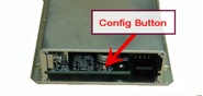
- CONFIG Button
If certain parameters within the M7 GX transponder are modified in a manor that causes the modem to cease functioning or if the user cannot enter the command mode via the “+++” method, there is a small push-button inside the M7 to assist. This “CONFIG” button may be pressed at any time, and forces the M7 GX into a known state. The CONFIG button is located inside the M7 GX. Remove the rear cover, exposing the circuit board and he button as shown below.
The default settings that the M7 GX will revert to when the CONFIG button is pressed are:
- Serial port 9600 baud, 8 data bits 1 stop, no parity
- Serial port flow control is off.
- ATCT setting set to 60000 (60 second time-out)
Even though the serial baud rate reverts to 9600 baud when the CONFIG button is pressed and the IO port is RS232, it will revert back to the settings programmed into the M7 GX once the Command Mode is exited.